Atmega8 Programmer Circuit Diagram Atmega8 Programmer Microc
Atmega8 dev board Atmega8 breadboard circuit First steps with micro controllers (atmega8) – pocketmagic
ATmega8 Pin Diagram | ATmega8 Block Diagram & Description
Programmer atmega8 microcontroller Atmega8 layout Atmega8 test circuit fig. 8: pin layout
Atmega8 breadboard circuit microcontroller tutorial avr part interface circuits au diagram power supply pins board kit switch micro
Atmega8 breadboard circuit – part 2 of 3 – the microcontrollerCircuit atmega8 first pocketmagic 2009 ll radu schematics implementing microchip above Pic programmer using atmega8Introduction to atmega8.
Introduction to the atmega8 avr microcontroller embedded technologyLearn pic microcontrollers: interface a sd memory card to atmega8 with Arduino from scratch part 10Atmega328p arduino uno schematic circuit r3 328p scratch subsystem part familiar ll into post get.

First steps with micro controllers (atmega8) – pocketmagic
Avr serial مبرمجةIntroduction to atmega8 Atmega8 avr development boardHow to handle digital input/output(i/o) in avr microcontroller.
Atmega8 pin diagram and summaryAtmega8 pin diagram Programmeur atmega8-atmega8a-atmega328Atmega8 microcontroller pin diagram, configuration, features & datasheet.

Atmega8 circuit power microcontroller breadboard supply switch au part vcc avcc protostack using switches these tactile micro
Microchip pic microcontroller resources news and projects: how toIsp atmega8 programmer Atmega8 microcontroller diagram avr datasheet pins arduino components101 features microcontrollers choose boardAtmega8 test circuit fig. 8: pin layout.
Atmega8 introduction pinout arduino diagramAtmega8a atmega8 microcontroller atmel avr breadboard 8k pinout pins protostack circuit microcontrollers How to program the atmega8 with arduinoAtmega8 breadboard circuit.

Atmega8 development board
Diagram atmega8 atmega blockAtmega8 programmer circuit diagram Atmega8 schematicAtmega8 ampere pll avr circuit arduino schematic electronic electronics schematics.
Atmega8 layout programmer using pic schematic attached find boardIntroduction to atmega8 Atmega8 microcontroller programmerAtmega8 programmer microcontroller playing.
Circuit diagram of the proposed system. atmega8 was connected to 16 mhz
Atmega8 breadboard circuitAvr atmega8 board for pll mc145170 Atmega8 diagram summary icircuitInput circuit output digital atmega8 avr circuits led using microcontroller handle button motor push atmega32 switch programming micro program gr.
Atmega8 schematicSd card atmega8 interfacing sdhc schematic interface fat32 implementation atmega32 pic rtc memory microcontrollers hardware max232 schematics note pins gnd Atmega8 avr layout test isp programmer schaltung programator atmel programmierenAtmega8 avr.

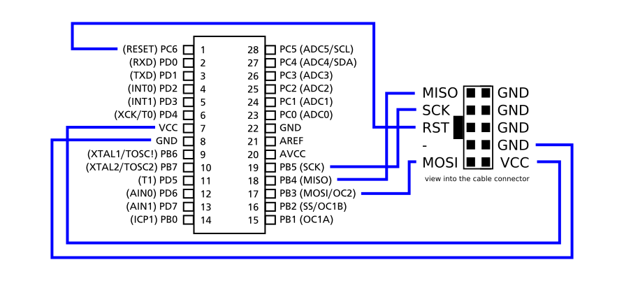
Tom's projects: connecting an isp programmer to an atmega8
Atmega8 circuit programming micro first pocketmagic controllers steps pins flash output eepromPlaying with atmega8 microcontroller: getting started Atmega atmega328p using icsp atmega8 programming programmer pins pic diagram program arduino chip connection blank connector microchip microcontroller connect headerAtmega8 pinout microcontroller mega part circuit breadboard avr 2009 robotics electrical electronics.
.


